Heater Switch, Voltage & Current Sense

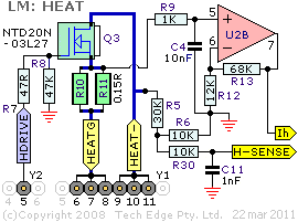
High current FET (Field Effect Transistor) Q3 controls the sensor's heater circuit.
Return heater current HEAT- flows through Q3 and then to the ground level point HEATG
(which returns to the main board).
The microcontroller's unbuffered HDRIVE signal controls Q3
in PWM (Pulse Width Modulation) fashion.
Inrush current to the FET's gate is controlled by resistor R7.
Resistor R8 ensures the FET switches OFF if/when the microcontroller's
HDRIVE signal is tri-stated (for example, during power-up).
Heater current is measured by sensing the small voltage developed across resistors
R10 & R11
that together form a 75 mΩ (75 milli Ohm, or 0.075 Ohm) high current resistor.
R9 & C4 form a simple low-pass filter for amplifier
U2B, which has a gain of (12+68)/12 = 6.67 times.
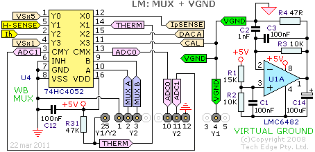
The amplified voltage Ih (perhaps Vih may have been a better name?) is fed to the MUX described below.
As the maximum voltage to the ADC is 5.0 Volts, this translates to 750 mV (5.0/6.67 Volts) across
the 75 mΩ sense resistors, so an instantaneous current up to 10 Amps can be sensed.
Regarding power dissipation, at an average heater current of 2 Amps, which is a common maximum operating current,
the voltage across R10//R11 is 150 mV and the power dissipated by each resistor is 0.15 * 2/2
= 150 mWatt. This is within the power rating of these resistors.
The main board's 3 Amp fuse should protect these resistors during a fault condition.
Q2's ON resistance at 10 Amps is less than 25 mΩ, just 250 mWatt is dissipated at this current,
and less at normal operating currents, so just a small heatsink area is needed for this part.
R5 & R6 constitutes a ¼ divider, and the resulting voltage H-SENSE
is fed to the MUX described in the following section.
The main board also has a similar voltage divider which is used to measure H+SENSE which is
the voltage at the positive end of the sensor's heater.
Knowing these two voltages, and the heater current (from Ih), allows accurate measurement
of the heater's impedance. This information is used during the heater's warm-up phase and to vary the power
to the heater, thereby taking into account any supply voltage fluctuations, to the controller itself.
After the warm-up phase, a PID (Proportional Integral Derivative) controller is activated (in software)
to maintain the sensor temperature at the correct level. Note: For Bosch LSU
sensors, the heater PID control variable is the internal impedance of the Nernst sense cell,
known as Ri. This gives more accurate sensor temperature control.
For NTK UEGO sensors, the heater impedance is the control variable to the
heater PID controller, which is less accurate.
|


